Garage Light Controller
This post contains Amazon Affiliate links. If you click the link and make a purchase I receive a small commission to keep Makercise up and running. View my privacy policy here.
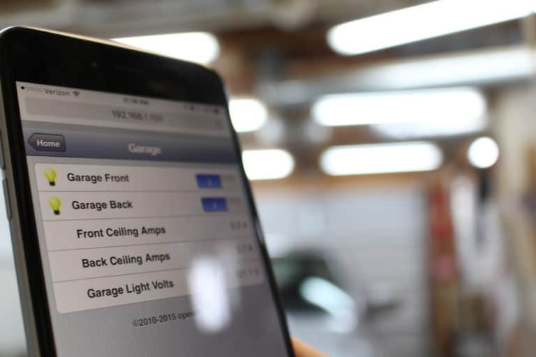
For the longest time, I have wanted to control my garage lights with something other than light switches. Why? I don’t have a switch by the back door, but I do have my phone with me 99.5% of the time I go through that door. Using my phone to control the lights would be convenient. I consistently leave the light on overnight unintentionally. Although not the biggest waste of energy the circuits do draw 5A and 7A respectively so it adds up. I did not however want to lose the ability to control the lights with the existing switches. And I didn’t want power blips, code bugs, or network issues to keep me from being able to use the lights as I always have.
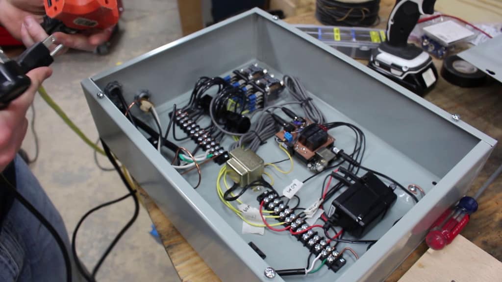
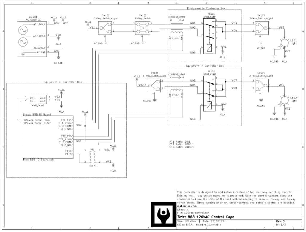
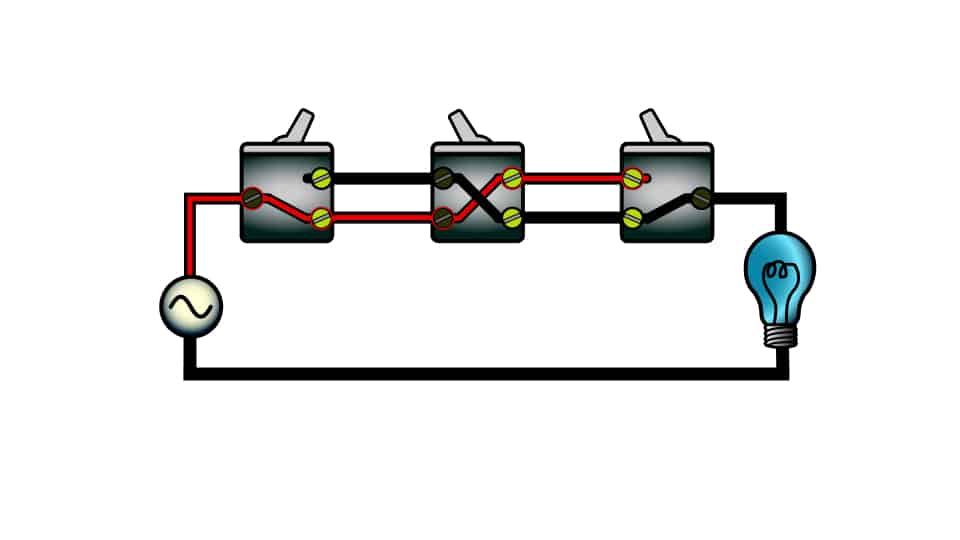
Last fall I posted an article detailing the operation of multi-way circuits including how a relay could play into multi-way switching. The BeagleBone Black (BBB) is the brain of the controller. I selected an enclosure that would fit between the floor joists yet accommodate the parts, relays that were rated at 20A in the normally open and normally closed positions, latching relays for the low voltage expansion board, and potential and current transformers to facilitate measurement of analog waveforms. Caution: many relays have separate ratings for NO and NC contacts. I selected terminal blocks also rated at 20A. Well oversized for the measured lighting loads but sized according to the actual circuit which is 20A.
There are two really important features of this controller. The first is the latching relays. One thing I didn’t want happening was a power blip to change the state of the light switches. If I am in the shop and a lightning stroke blinks the lights, whether or not the BBB (which isn’t on a UPS) loses its mind, I want the lights to come back on if they were previously. On the other hand when the power returns, I don’t want to go around turning off lights that were previously off. Obviously the lights go out without utility feed, but when the power comes back, the lights should remain in the same state. Hence the need for the low voltage latching relays.
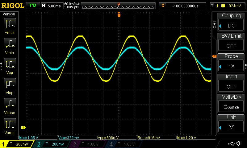
The second really important feature is the current transformer. Without this part, the BBB would have no concept of whether the lights are on or off. When people switch multi-way circuits, they assess the state of the light by–no surprise–looking at the light. I could have added a light sensor, but the current transformer (CT) does double duty by enabling course metering and state observation. Note that I put two turns through the CT to increase the resolution of the CT. Also note that both the traveling pairs pass through the CT. It is possible to monitor both travelers because we don’t really care which traveler is switched onto the load and the entire load current must go through the current transformer on one of the travelers.
Currently, I use the programmable real-time units (PRU) on the processor of the BBB to collect samples from the analog to digital converters. However, I would like to modify the code to do more. I have pondered some enhancements that I probably will never implement. I can get high resolution samples and plot them, but I believe the sample rate could really be sped up yielding very interesting data–if the input filters were modified. I could also envision a zero current or zero voltage crossing switching that is based on timing observed in actual event logs generated by the system. Better data availability such as exposing volts, amps, apparent power, watts, vars, power factor, harmonics, etc would also be nice. It would be cool to generate waveform plots using something like matplotlib and display them after a switching event on the web page. I am really a fan of the BBB now. I love the PRU and the ability to do real-time tasks kicked off from the python space within the Linux kernel.
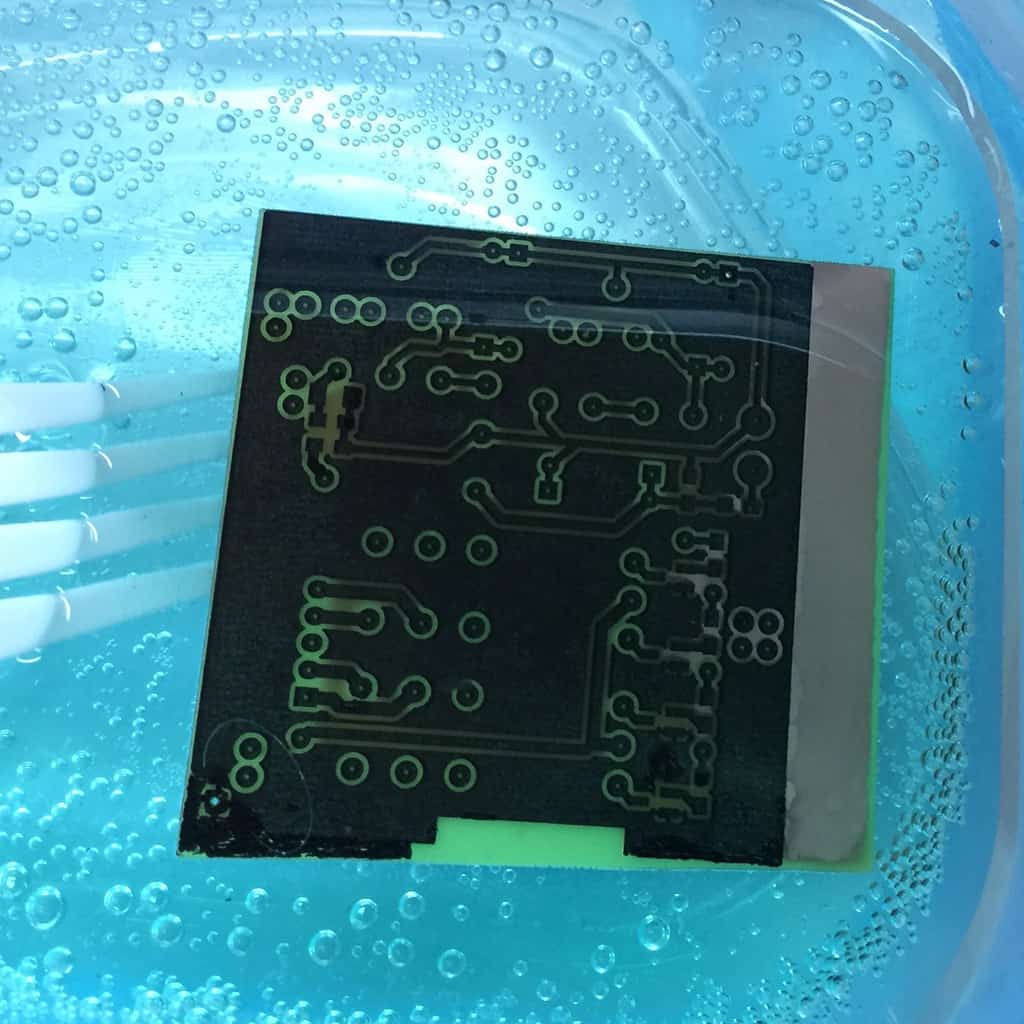
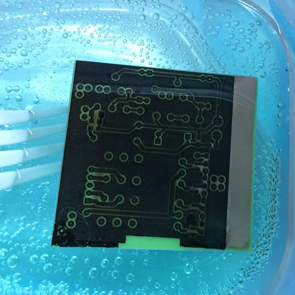
I took the time to etch my own board, but you could have the board fabricated by others. I include low pass analog filters on the input as well as some diodes to clamp circuit voltage based on max 1.8V for BBB. Originally I did not include these on my board, but I updated the circuit after I decided I needed them to compensate for my quickly prototyped code. I have included a parts list below in case you want to try building a similar circuit. I have also attached a link to the pdf versions of the schematics and panel layout as well as the kicad and librecad files in case you want to modify anything to facilitate your own project. [UPDATE: since writing this post I upgraded the garage light controller to run on openHab.] I have included the code I [initially] use on the BBB. I would qualify these resources as minimum viable project. There are comments in there, but the code could use lots of work. I do not include smaller discrete surface mount components in the bill of material be sure to order some if you don’t have reels of SMD componests stacked in your garage. ;-P
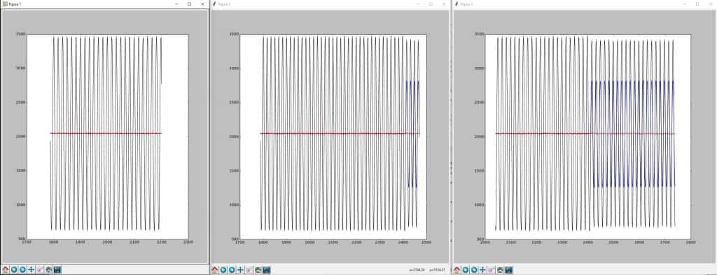
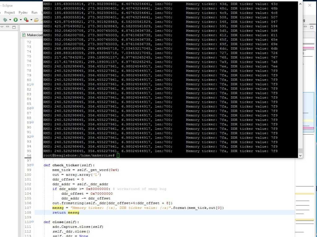
One of the items that was frustrating during development of the code is that the PRU code needs to be restarted intermittently when I switch the load on and off. The python class takes care of this automatically, but it really shouldn’t be necessary. I expect this is a result of my limited understanding of the PRU. I have an image that shows the code executing and then locking up.
Bill of Materials:
| Qty: | Used In Project: | Part Numbers | Amazon.com Links (Affiliate) |
| 1 | Box | CS16124 | http://amzn.to/1RN8eDp |
| 4 | Latching Relays | G5RLK1EDC5 | http://amzn.to/1LpEGz4 |
| 2 | Correct Relays | KUHP-11A51-120 | http://amzn.to/1RN7VZm |
| 4 | CT | Non-Invasive Current Sensor – 30A | http://amzn.to/1LpFgNm |
| 4 | Audio Jack |
Audio Jack 3.5mm | http://amzn.to/1YYjy51 |
| 1 | BeagleBone Black | Rev C (4G) Single Board Computer Development Board | http://amzn.to/1LpEAaC |
| 1 | Rigol Oscilloscope | DS1054Z | http://amzn.to/1nPBQYF |
Files:
20160316 Plans Makercise 120VAC Controller
References:
https://makercise.com/3-way-4-way-multiway-switching-how-it-works/
http://mythopoeic.org/bbb-pru-minimal/
http://www.embedded-things.com/bbb/understanding-bbb-pru-shared-memory-access/https://github.com/pgmmpk/beaglebone_pru_adc
http://kicad-pcb.org/download/ubuntu/
http://www.instructables.com/id/PCB-etching-using-laser-printer/?ALLSTEPS
http://www.instructables.com/id/Stop-using-Ferric-Chloride-etchant!–A-better-etc/?ALLSTEPS
https://learn.adafruit.com/introduction-to-the-beaglebone-black-device-tree
Stream-of-consciousness style code development journal for my own reference:
20160210:
Took a day off from work to get some coding done today. I really want to get a child class created based on beaglebone_pru_adc. The features I want to add are:
Analog log: This will be implemented as a circular buffer in the DDR memory. Pointers stored in PRU memory and updated. The delay function in parent Capture class still works to slow down these samples. The function will sample AN0, AN1, AN2, and store n (the number of ticks from start). Initially this wont be a truly discrete time log (this could be added later if the BBB comes with counter based interrupts). The method should provide a return in python that orders the samples by converting a circular buffer into a dictionary that indexes each sample as a linear sample list.
Event log: This method will dump the Analog log before and a selectable duration after the method is called to a file for analysis.
RMS metering: This will be implemented based on the analog_log storing roughly discrete-time samples.
Zero crossing switching: This will be implemented as the ability to set output states on the basis of an anticipated future zero crossing. Time lag for output operation should be specified in python and set in the
TODO: address n ticks roll over gracefully – probably by forcing a roll over.
It took me a while to play with the length of the buffer, the caputer delay, and the size of the analog_log.
The next step is to get the rms metering calc setup and to put the class into a scheduling routine that spawns a process to grab samples.
20160211:
Worked on adding threading to the class.
Noticed a problem where the run() method stops updating the contents of buffers in python when heavy load is switched. Perhaps the surge is causing an interruption in memory mapping, or the PRU is ceasing to execute the code.
20160213:
Continued debugging the PRU lock-up. DDR and PRU ram mappings still accessible to get and set memory. Need to restart. PRU_ADC code doesn’t give the ability to reload firmware to restart…had to add self->started = 0 to the close() method…segmentation fault. More and more memory issues. Now I can’t boot the BBB.
Flashed SDcard with 2016-01-24 Debian BBB image
put card in and booted
ssh in as default debian:temppwd
followed:http://elinux.org/Beagleboard:BeagleBoneBlack_Debian#Flashing_eMMC
rebooted and looked for cylon/nightrider light patter
after light off remove SDcard
ssh in as default debian:temppwd
setup makercise account: sudo adduser makercise
sudo usermod -a -G sudo makercise
ssh in as makercise
apt-get update && apt-get install python-serial python-setuptools python-dev python-smbus python-pip
20160214:
Downgraded because of segmentation fault described in PyBBIO
apt-get update && apt-get install linux-image-3.8.13-bone70
debugged memory initialization. Order of pru_init matters since changing AN_LOG_I to non zero starts code. If all other pointers aren’t established it blows away other stuff like the eyecatcher.
Implemented the pacemaker to keep the PRU loaded and going. Toggling the relay causes the PRU to crap out.
20160216:
Code seems to have a memory leak.
20160217:
Memory leak found and fixed. self.messages
Now back to having problems with reading data from DDR. roll back of code unsuccessful. Can’t figure out why the index isn’t incrementing in DDR.
20160218:
Went back to the original beaglebone_pru_adc example code. It doesn’t work any more. Probably goofed something up with direct memory access as root. Wow! Reimaged the eMMC onboard memory downgraded to 3.8 kernel. Then made a backup /dev/mmcblk1 (external SD card) from image on /dev/mmcblk0 (internal eMMC). Reverted to old firmware.p and memory leak code. Cleaned up memory leak the initiated. I’ll check it in the morning, but so far so good.
20160311:
Backed up and now to implement the light bulb counter and the timer. Bulb counter too noisy. Timer implemented.
TODO:
Move I/O switching into the Makercise Controller class. This would improve the timer functionality

