Shaper Column Front Casting and Column Assembly
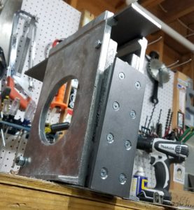
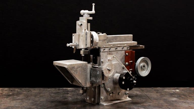
As you know I started building a Gingery Shaper recently. In this part of the series, I use the lost foam casting method to create the column front. Then I add the vertical ways and assemble the column front. I now have the initial column assembly completed. Note that only two fasteners are used because I need to adjust the front column so the vertical ways are aligned with the ram slide. Watch the full project video and then check out the detailed article below.
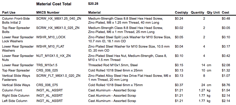
I have now spent 27 hours minimally and 31 hours with optional items like hoist fab, hot wire cutter fab, and wasted time in the shop on this project to date. To date, I have used $20 worth of materials and almost $1 of fuel. Here are the results: materials, fuel, and timesheet.

 This post contains affiliate link. I make money if you use these links to buy things.
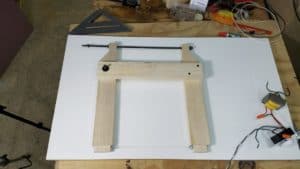
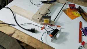
One of our Makercise patrons requested that I attempt some lost foam casting. I decided the column front would be a good place to try it. I built a simple hot wire foam cutter to make this possible. Currently I have just clamped it to the side of a scrap of melamine, since this was just for proof of concept. The cutter is made from some scraps from poplar boards (I milled the boards using my homemade chainsaw mill), a transformer from a broken lamp, dimmer switch, stainless steel hanger wire (this is 22.7kg or 50lbs wire with strands that are 0.33mm or 0.013″–not information found on the package). I referenced Grant Thompson’s styro slicer video to get going, but I opted not to save $5 by not buying a pack of springs at the big box store. During my testing, I observed why the springs are a common design element: the wire stretches as it warms. My rig is tensioned by a long threaded rot opposite a fulcrum from the wire attachment eye hooks, therefore I have to tension the wire after heat is applied. This will probably cause the wire to burn out faster, but it seems to be working for now. Eventually, I may make a more permanent setup.
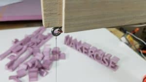
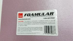 After making the hot wire foam cutter, I cut a handful of foam letters and shapes to get comfortable with the cutter. I decided to cast some test coupons before spending time making the column front pattern. I did not had good luck with my one previous attempt at lost foam–most likely because the sand was too dry. For this new attempt I decided to be more scientific with my test coupons. I placed one in the sand bare, one in the sand with a partial coating of plaster of paris, and one in the sand with a full coating of plaster of paris. The plaster of paris did a phenomenal job of preserving surface detail and keeping sand from sticking to the coupon.
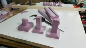
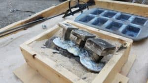
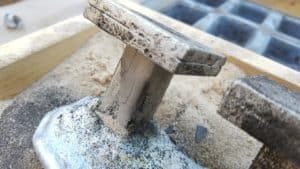
Based on the coupon success, I cut parts for the column front and used hot glue to assemble it. I melted a half pot of metal using the last of the ingots left from the lathe project. I am running out of metal and will have to start breaking down the transmission housings before casting again. (Oil burner scrapping side project in my future?) I also felt like my propane tank was on ‘E’ or almost empty. Short story: I cast the part without enough metal. I believe the part will be useable, but the sprue and gate are nearly absent. I’d rather be lucky than good.
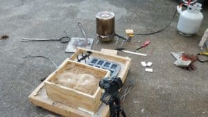
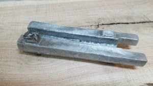
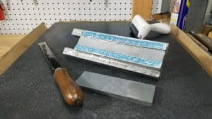
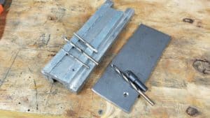
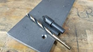
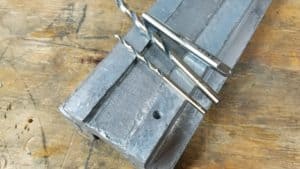
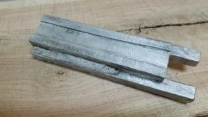 Before I started scraping the column front, I use a portable bandsaw and 12″ Disk Sander to clean up my castings before machining or scraping. Although I got mine from Harbor Freight, mine are similar to the Dewalt the Grizzly versions of these type tools.Then I put a sheet of sand paper on the surface plate to get it very close before proceeding to scraping. I spent about 1.75 hours cleaning up the castings before proceeding with scraping. I spent about 2.5 hours scraping in the surface to very close to flat. I cut a piece of 75mm x 6mm 1018 cold rolled steel to the length of the column front. Then I match drilled one hole to 5mm. I separated the steel from the casting and used a M6x1mm (that is a 6mm diameter with 1mm thread pitch) tap to cut threads in the aluminum casting. I enlarged the hole in the steel to 6mm to allow the fastener to freely pass through the part. I countersunk the hole with a 90degree 3-flute bit. This was not the right tool for the job in my small drill press with a relatively high slowest-speed. The chatter was redonk. The 6-flute 72 degree countersink (black bit pictured below–my McMaster Carr order hadn’t arrived yet with my new 3-flute) has much less chatter. A single flute bit is probably the right way to go. I fastened the vertical ways to the column front with a single machine screw, M6x1mm. I clamped the other end and drilled, tapped, and countersunk in a similar manner. Once I had two ends secured with fasteners, I drilled, tapped, and countersunk the remaining six holes in a batch.
I drilled 3mm pilot holes in the front of the column side casting for the column front mounting bolts and a 10mm hole in the back rear of the column side castings. I made a rear spreader with an M10x1.5mm threaded rod and some M10 nuts. Then I clamped up the column front and column sides. I match drilled the top holes for mounting the column side to the column front to 5mm. I used a 6mm drill to enlarge the holes in the sides. I used an M6x1mm tap with the holes in the sides as a guide to tap the holes in the column front. Then I installed two M6 bolts. This allows the front to swing so it can be adjusted perpendicular to the ram slide. After all this work, I took the assembly to my table saw and noticed a fairly bad misalignment. Basically, I did not get either the top or the bottom of the column planar, the top ledges being the preferred feature to get coplanar. I decided to enlarge one of the column side holes with a small round file enough to persuade the sides into alignment. I’ll have to be careful to clamp the front well when installing the remaining fasteners in the column front. I also took the opportunity while at the table saw to enlarge the channel atop the column where the ram slide lives. As cast the column front width would be too tight for the ram slide and gib. I shaved off a few millimeters to give room for the 6mm x 3mm CRS gib. Finally, I cut a length of 6mm x 25mm CRS for the top rear spreader. This completes the initial assembly of the shaper column.
