3-Way 4-Way Multiway Switching – How it works
Do you know how 3-way 4-way multiway switching works? Check out this post and video to see it broken down with animation and a free printable.
Multiway switching is used when you want to be able to turn on or off a load such as a light from multiple locations. For instance in my garage, I can turn on and off the lights from the staircase and the door. This is what’s known as three-way switching in the US. It would be really convenient if I could switch on the light from the back door instead of having to trip over stuff making my way to the switch. Let’s look at the details of how multiway switching works and maybe I’ll get a switch by the door in the not-so-distant future.
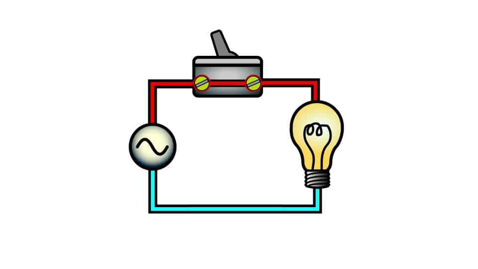
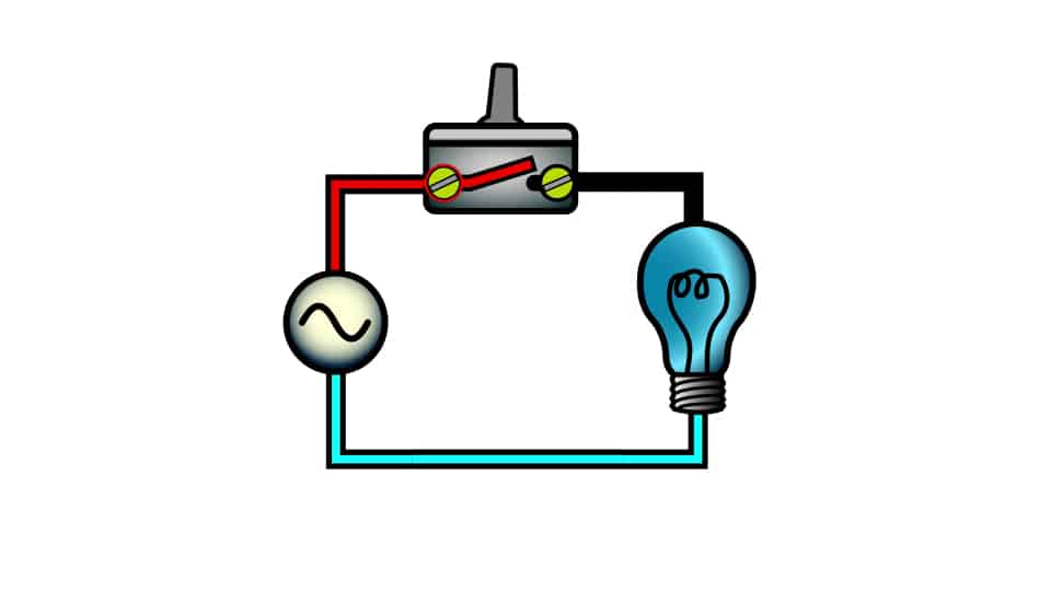
First let’s consider how power makes it from a source to a load in a simple configuration. In simple switching, you have a single switch in line with the load. In this video I’ll be talking about lighting loads but the concept is applicable to other types of loads. When the switch is closed voltage from the source is presented to the load and establishes current flow this causes the light to illuminate. When the circuit is open current can’t flow from the source to the load and light is turned off.
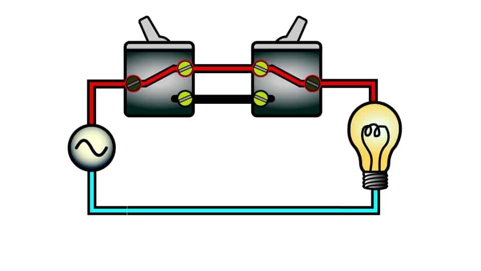
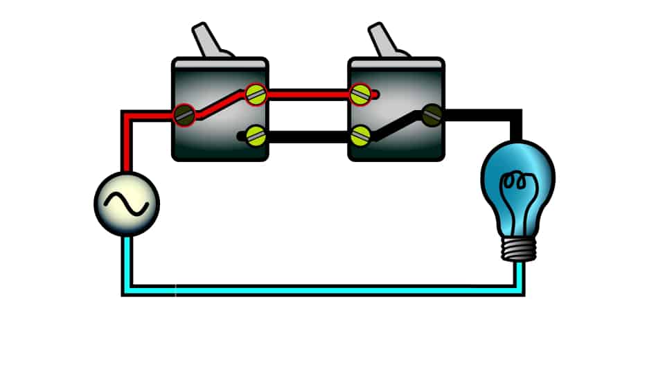
If we want to perform switching at two locations however we need three way switches. Three way switches are special switches with three terminals. On the switches I bought one terminal is a gold screw and the other two are black screws. When the switch is down the gold contact is connected to one black screw, and when the switch is up it’s connected to the other black screw.
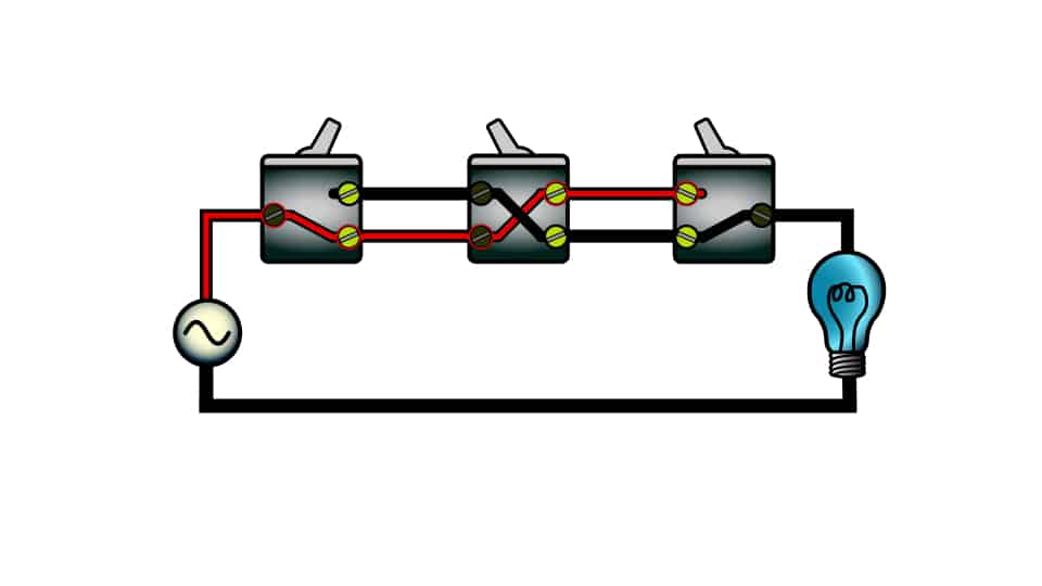
In a three way circuit, the first switch is connected to a source. The second switch is connected to the load. The two switches are connected together using travelers. Traveling pairs are really the key to multi way switching. These wires allow the circuit to toggle when any switch is toggled. When the first switch is toggled the top traveler is energized. When the second switch is toggled, the energized traveler or t he unenergized traveler is switched onto the source side of the load. Depending on which traveler is connected the load will be either on or off. Either switch can be used to control the load.
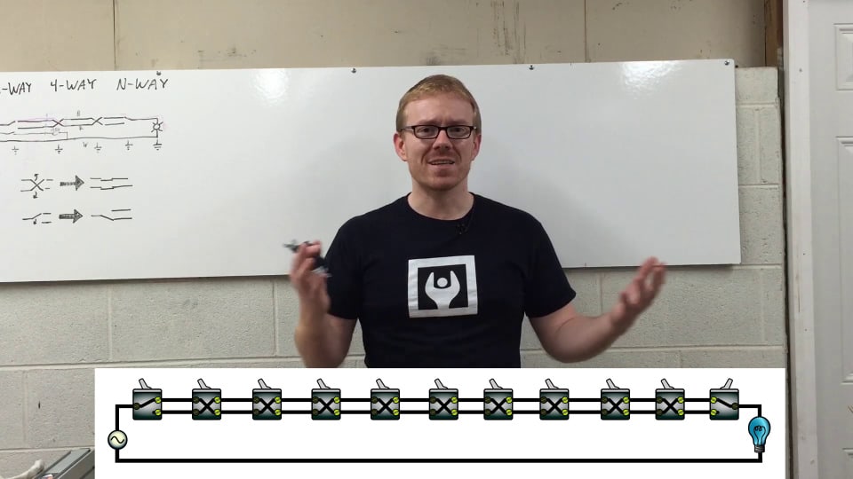
The addition of one four-way switches in the circuit give you additional locations from which you can switch the load. A four-way switch works by swapping the connection s between the pairs of terminals. On the switch that I bought two of the terminals are black and two of the terminals are gold. With the switch in one configuration, the black terminals are tied directly to the gold terminals. They go straight through. When the switch is toggled, the black terminals are swapped relative to the gold terminals. Such a configuration is helpful because it allows the traveling pairs to be rolled.
Through this functionality, the same concept from three-way switching can be extended to multi way switching. In multi way switching one or more four way switches are wired between the three way switches. When the four way switch is toggled the traveling pairs downstream from that switch swap energization states. Because at all times one of the traveling pairs is always energized, changing the state of any switch in the circuit changes the state of the load. It is possible to add as many four-way switches to a multi way circuit as you wish. However it doesn’t scale well.
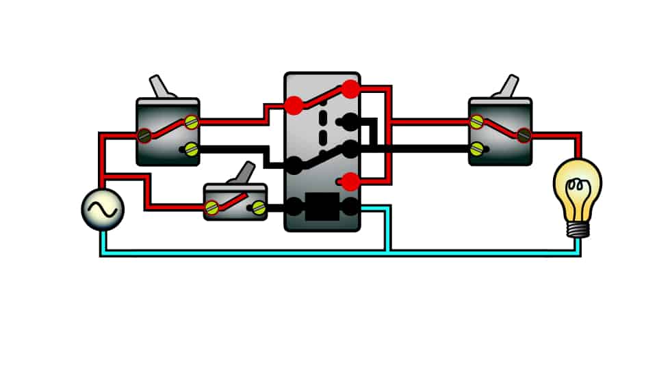
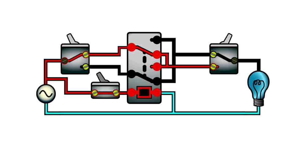
If you have lots of switch locations or if you want to do something fancy like switching based on a timer, motion detector, or some other concept, using a relay is the most straightforward way to make these applications possible. So how do I make a relay replicate the function of a four way switch? Well, I use a double pole double throw relay.
Here’s how a double pole double throw relay operates. There are two sets of switch es (or poles) in the relay. Each pole has a common terminal that can be connected to one of that pole’s other two contacts. Both poles toggle when the relay coil is energized. OK this doesn’t look like a four way switch.
The four way switch is a four terminal device. But the double pole double throw contacts have six terminals. Well, we can wire up those contacts to function as a four-way switch. Let’s rearrange the contacts on this diagram so that we can more easily see how this is done. We’ll jumper together the two outside contacts and the two inside contacts. The two outside contacts will be connected to the top traveler downstream from the relay. The two inside contacts will be connected to the bottom traveler downstream from the relay. The common terminals will be connected to the upstream traveling pairs. Now our relay functions just like a four-way switch. All we need to do is energize the coil to get the “switch” to change states.
Multiway switching can be confusing. This is mainly due to historical wiring practices where a single multi wire cables might be pulled to the switch location from a light receptacle or where a neutral wire was not required in all boxes. In older installations, you can run into lots of variation. When I run into confusion associated with multi way switches, I find it really invaluable to diagram out the switches, the cables, the boxes, and how they need to be connected. I hope this printable will help you if you run into a confusing situation with multi way switching. Let me know if you have feedback.
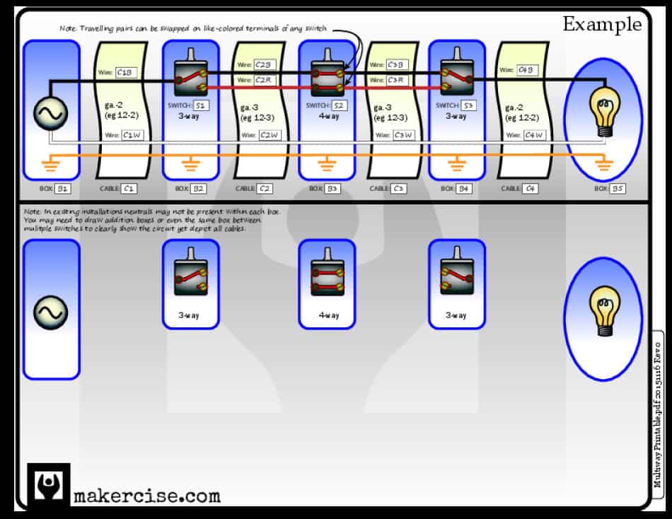 I really think it’s important to clearly label the switches, the cables, and the boxes. It is critically important to confirm which cable runs between each location and label those cables to keep track of them. Put those label on the diagram too. Sketched it all up on paper, then get out the strippers and wire nuts. That approach is much more efficient for me versus trying to on-the-fly figure out which wires are travelers, source, loads, and any inherited monkey business in the circuit.
Although wiring household circuits can be hazardous, I encourage you to understand multiway switching. Reach out to a qualified electrician where you have doubts.






Where can I find the relay that you have in your video?
Wow! Sorry for the long delay in responding. I have to wade through a thick stack of spam comments to get to genuine ones.
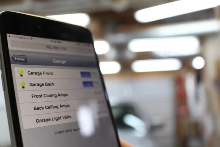
Here is an Amazon affiliate link to the part shown in this video: http://amzn.to/2cTQqwP However, the normally close poles of that relay are only rated for 3A which is probably not useful for most house lighting circuit applications. In my Garage Light Controller post, I diagram out the circuit that I use to actually control my garage lights from my iPhone: https://www.makercise.com/garage-light-controller
In that project I used this relay http://amzn.to/2dk7H0r which is rated for 20A on both the NO and NC poles of the relay. Hope this information doesn’t come too late.